Spec sheet · REV A

PSP Liquids · Avionics · Summer 2026

04Project log

PSPocketPocket Game Console

Handheld game-console PCB used as a hands-on embedded systems + PCB design onboarding project for incoming Purdue Space Program Liquids members, run by avionics lead Mo over the summer before the fall semester.

Purdue Space Program logo
MCU
STM32C031K6T6
Display
16×16 SMD LED matrix
Team
~8 · Liquids Avionics

Back to projects

Scope

Board centers on an STM32C031K6T6 driving a 16×16 SMD LED matrix through daisy-chained SN74HC595D shift registers, with an accelerometer, tactile button array, buzzer, and dual potentiometer inputs. Parallel workstreams covered display firmware, input code, routing, and software architecture.

My notes

  • Designed the MCU schematic in KiCad after Altium licensing blocked local work; kept the sheet interoperable with the team’s Altium 365 workspace.
  • Selected and locked N- and P-channel MOSFETs for the LED matrix high-/low-side drive path.
  • Contributed footprint and voltage-divider decisions on the input/sensor circuitry.

Stack

  • Altium Designer
  • KiCad
  • STM32C031K6T6
  • STM32CubeIDE
  • SN74HC595D
  • MPU6050 / LIS3DH
  • PlantUML
  • GitHub

Exhibits

5 figures

Fig. 01

LED matrix drive schematic
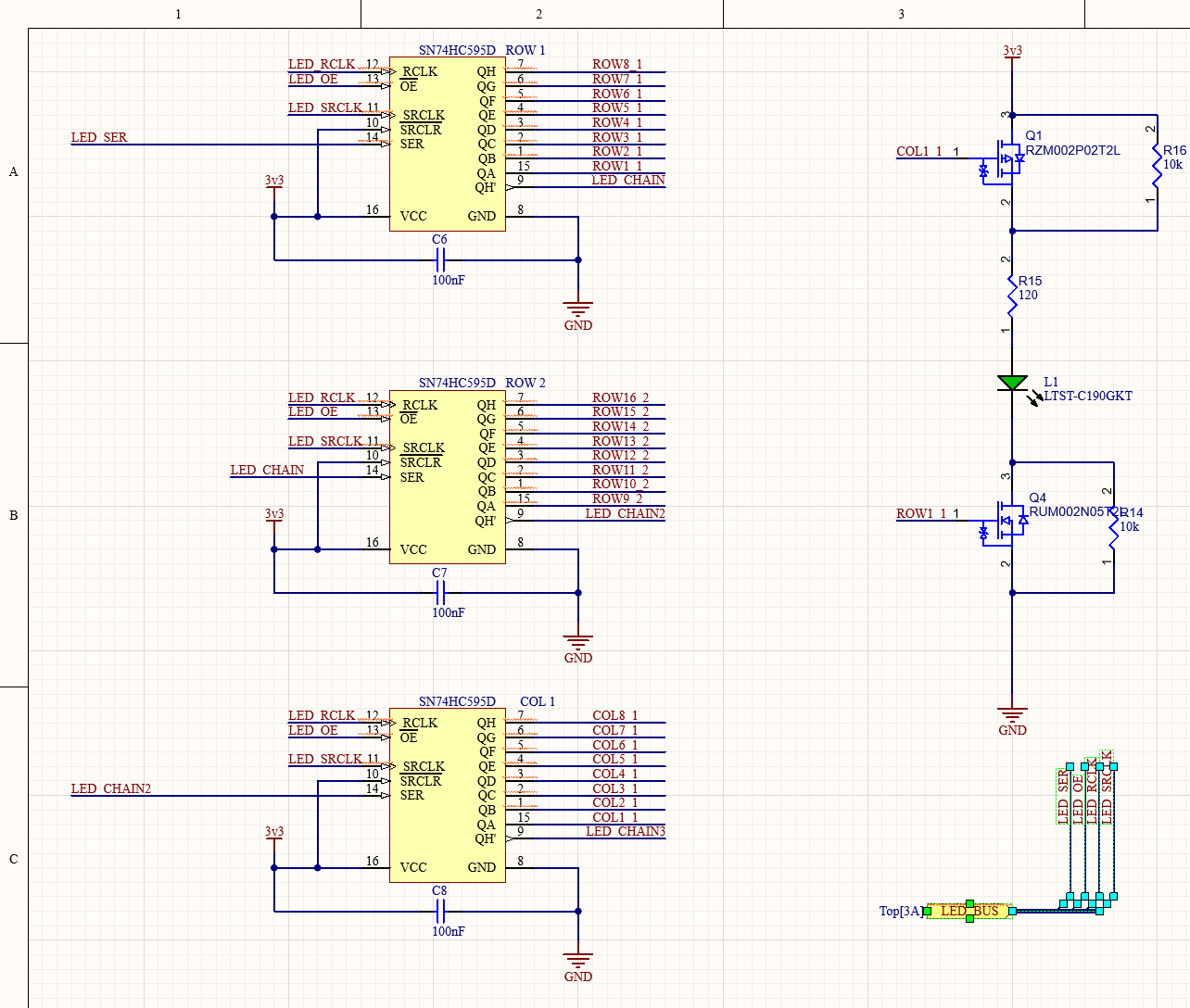
KiCad/Altium schematic of SN74HC595D shift-register chains driving a single LED pixel through P-channel and N-channel MOSFETs
CaptionDaisy-chained SN74HC595D row/column drivers with P-/N-channel MOSFET pixel path (RZM002P02T2L high-side, RUM002N05 low-side) and 120Ω series limiting.
Fig. 02

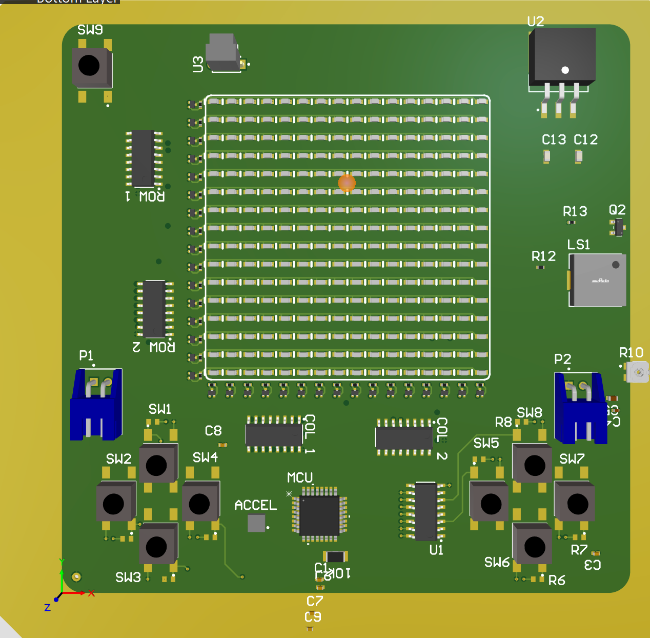
PCB — bottom layer 3D render

3D render of the PSPocket PCB bottom layer showing the LED matrix, MCU, shift registers, accelerometer, buzzer, and button array
CaptionPopulated board view: 16×16 SMD LED matrix, STM32 MCU, ROW/COL shift registers, ACCEL, LS1 buzzer, and SW1–SW9 tactile inputs.
Fig. 03

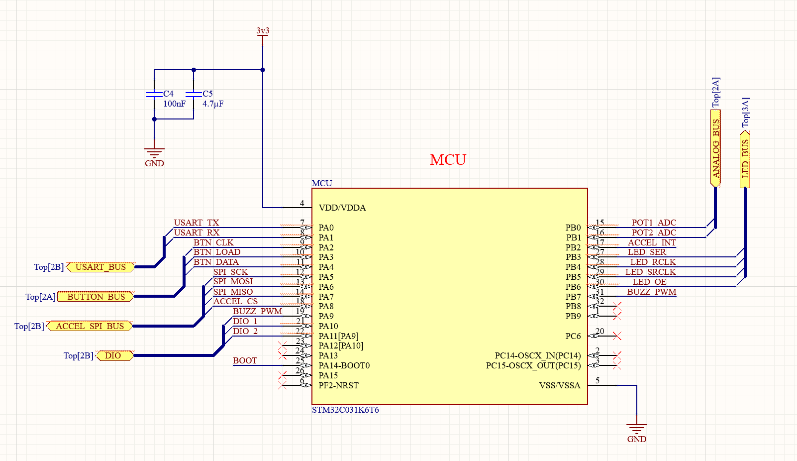
MCU pinout sheet

Schematic sheet of the STM32C031K6T6 MCU showing pinouts for LED, button, accelerometer SPI, potentiometer ADC, and buzzer buses
CaptionSTM32C031K6T6 pin assignment — LED bus, button bus, accel SPI, dual pot ADCs, and buzzer PWM with local 3V3 decoupling.
Fig. 04

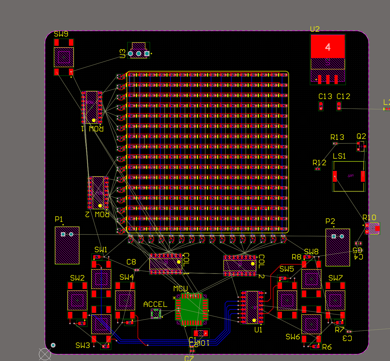
PCB layout (CAD)

2D PCB layout of PSPocket showing LED matrix footprints, MCU, shift registers, buttons, accelerometer, and buzzer on a black CAD canvas
CaptionTop-down footprints and ratsnest: matrix grid centered, ROW/COL drivers flanking, MCU/accel south of the matrix, D-pad and face-button clusters at the corners.
Fig. 05

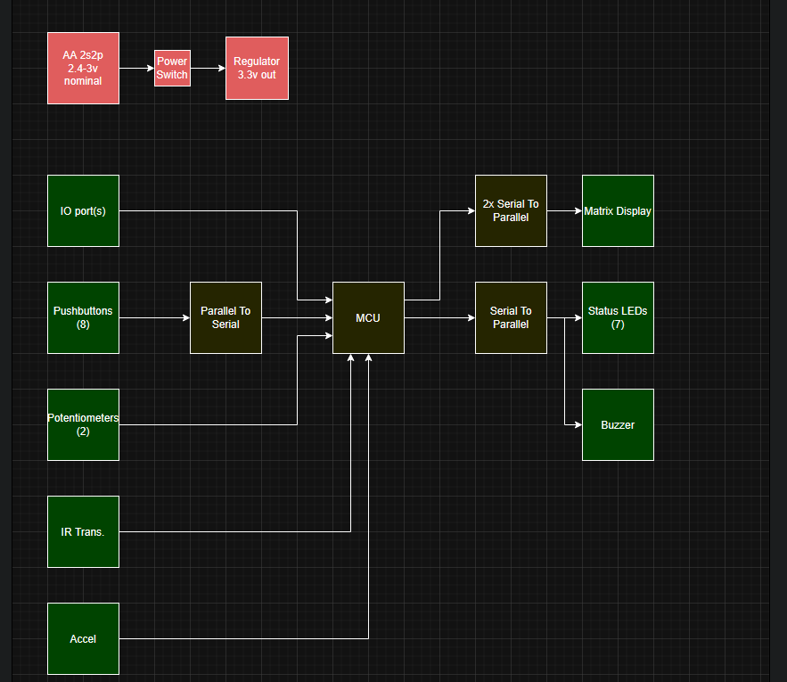
System block diagram

Hardware block diagram of PSPocket showing power path, MCU, inputs including buttons and accelerometer, and LED matrix outputs via shift registers
CaptionPlantUML-style architecture: AA 2s2p → 3V3 regulator → MCU; parallel-to-serial for 8 pushbuttons; serial-to-parallel for matrix + status LEDs/buzzer.